

Module Reconstruction, Mould Design & Validation
Reverse Engineering Solid & Surface Model and Moulding
Project Type: CAD/CAM, Reverse Engineering & Manufacturing Optimization
Role: 3D Scanning, CAD Modeling, Simulation, and Process Optimization
Overview
This dual-phase project focused on the design, validation, and manufacturing optimization of core and cavity moldsfor injection molding. It began with reverse engineering a physical part and extended into CNC machining process refinement — combining deep CAD/CAM knowledge with data-driven decision-making.
Approach
Using a Shining 3D Einscan HX, we scanned an existing part to generate a detailed point cloud. From this data, we created a high-fidelity CAD model and validated it with a range of simulations, including wall thickness, surface curvature, reflectivity, and more. This model then served as the foundation for designing a functional injection mold system, complete with runners, gates, ejector pins, and cooling channels — with strategic placement informed by simulation analysis.
In the second phase, we optimized the CNC machining processes for the core and cavity using NX Siemens. By simulating and comparing various cutting strategies (e.g. Zig, Zig Zag, Follow Part, Periphery) and experimenting with tool diameters, we significantly improved machining efficiency. Semi-roughing techniques were used to reduce material resistance and streamline finishing operations.
Outcome
The result was a fully functional mold system, backed by precise engineering decisions on injection gate placement and cooling flow. On the manufacturing side, we achieved a 28–34% reduction in machining times, cutting total durations from 5 hours to 1h44min (core), and 13 hours to 4h26min (cavity). Surface analysis confirmed accuracy within ±0.1 mm tolerances, and simulation error remained minimal at just 1.535% — demonstrating high alignment with real-world results.
-
![]()
Tooling Validation
-
![]()
Tooling Path Optimisation
-
![]()
Finishing
-
![]()
Simulation in Tool
-
![]()
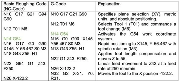
Example of G-Code of Milling
-
![]()
Lidar Scanned Part for Design
-
![]()
Flow Analysis Test for Moulding
-
![]()
Motion Simulation in Final Mould


Fast Forwarded Milling Simulation
Mould Ejection Simulation